
Universal I/O Module 16 outputs 16 inputs KNX ÆVO Series
Code: EK-FI1-TP-I
NewÆVO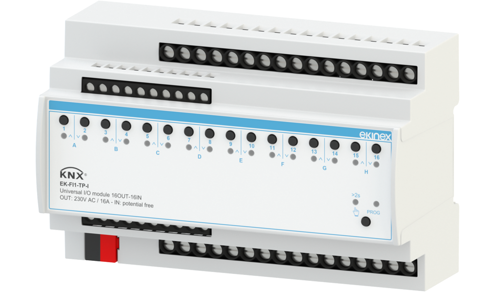
Description
ÆVO built to last - Unbreakable reliability and resilience for a hassle-free tomorrow. The EK-FI1-TP-I universal I/O module from the ÆVO Series allows you to control up to 16 groups of electrical devices, such as lights and valves, or up to 8 motorized drives, such as blinds and 3-way valves, independently and in any combination you like. For this purpose, the device has outputs equipped with potential-free bistable relay contacts that guarantee that the set control status is maintained even in the event of a power failure.
In addition, EK-FI1-TP-I allows the control of up to 16 drives, scenarios, up to 8 motors, dimmers, or the climate control of up to 8 rooms using the integrated thermostat/hygrostat function, by reading traditional commands and sensors equipped with potential-free contacts or passive NTC temperature probes. For this purpose, the device has 8 digital inputs and 8 analog/digital inputs that can be configured independently with interrogation voltage produced inside the device.
The product is equipped with buttons for manual control and LEDs for status indication; a button allows switching between automatic and manual operation. The device has an integrated KNX bus communication module and is designed for mounting on a 35 mm profile rail. Power is supplied via the KNX bus and no auxiliary power supply is required.
Technical data
Power supply
- •30 Vdc voltage via KNX bus
Outputs
- •Number: 16 (bistable relays)
- •Voltage: 230V AC
- •Current: 16 A
Inputs
- •Number: 16 (8 digital, 8 configurable analog/digital)
- •For passive temperature sensors (NTC 10 kΩ at 25°C)
- •For switches, buttons, or traditional potential-free sensors
Supply
The supply includes a terminal for connection to the KNX bus line. Any NTC temperature sensors to be connected to the inputs must be ordered separately.
Functions / Features
Configuration and commissioning
A detailed description of the parameters can be found in the device application manual. ETS5 or higher is required for configuration and commissioning. Application program for ETS: APEKFI1TPI##.knxprod
Technical documentation
Datasheet STEKFI1TPI_EN
STEKFI1TPI_EN• v. 1.0(03/11/2025)• PDF• 1,6 MB
Instruction Sheet FISPEKFI1TPIIE01
FISPEKFI1TPIIE01• v. 1.0(26/09/2025)• PDF• 3 MB
Application manual MAEKFG1FI1FH1TPI_EN
MAEKFG1FI1FH1TPI_EN• v. 2.0(01/09/2026)• PDF• 5,2 MB
Application software for ETS APEKFI1TPI03
APEKFI1TPI03• v. 0.3(21/07/2026)• KNXPROD• 1,4 MB
CE Conformity declaration CEEKFI1TPI
CEEKFI1TPI• v. 1.0(03/11/2025)• PDF• 883,7 KB
UKCA statement UKCADCEKFI1TPI
UKCADCEKFI1TPI• v. 1.0(03/11/2025)• PDF• 431,6 KB
Firmware MAEKFWUPD_EN
MAEKFWUPD_EN• v. 1.0(17/03/2025)• PDF• 980,9 KB
Firmware EK-FI1-TP-I_v.03.1.2_upgrade
EK-FI1-TP-I_v.03.1.2_upgrade• v. 3.1.2(02/07/2026)• ZIP• 7,9 MB
Setup Firmware Updater
Setup_FirmwareUpdater_1.0.0-dev2-6c755f4e• v. 1.0.0(01/04/2025)• EXE• 7,6 MB
Drawing DQEKFI1TPI
DQEKFI1TPI• DXF• 15,3 MB