
Description
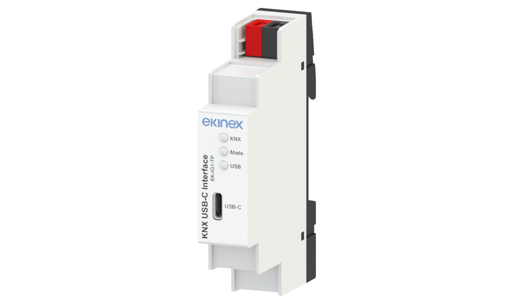
The EK-IG1-TP device is a bidirectional data interface between a PC or laptop equipped with a USB port and the KNX installation bus.
The EK-IG1-TP device can be used as a programming interface for ETS® software and supports KNX long frames. Long frames enable faster downloads to devices that support them and are required for KNX security.
The LEDs on the device indicate the operating status and communication errors on the bus. The USB connector (USB Type-C) is galvanically isolated from the KNX bus. Power is supplied via the KNX bus and the USB port with no external power supply required. It is designed for mounting on a 35 mm profile rail according to EN 60715.
Connections and Installation
- KNX TP red/black bus terminal connection
- USB Type-C connector for PC/laptop (maximum cable length: 5 m)
- Mounting on 35 mm profile rail according to EN 60715 (1 modular unit = 18 mm)
- No external power supply required (powered via USB and KNX bus)
Technical Data
Functions / Features
Configuration and Commissioning
ETS5 or later is required for configuration and commissioning. Application program for ETS: APEKIG1TP##.knxprod (## = version).
Documentation and Downloads
Technical Datasheet
STEKIG1TP_EN• v. 1.0(25/02/2026)• PDF• 558,4 KB
Instructions Manual
FISPIG1TPIEXXX00• v. 0(25/02/2026)• PDF• 592 KB
Application Manual
MAEKIG1TP_EN• v. 1.0(25/02/2026)• PDF• 937,1 KB
Application Software for ETS
APEKIG1TP10• v. 1.0(25/02/2026)• KNXPROD• 119,8 KB
CE Conformity Declaration
CEEKIG1TP• v. 1.0(09/02/2026)• PDF• 302,5 KB
UKCA Statement
UKCADCEKIG1TP• v. 1.0(25/02/2026)• PDF• 130,3 KB
CAD Drawing (DXF)
DQEKIG1TP• DXF• 602,8 KB