ekinex

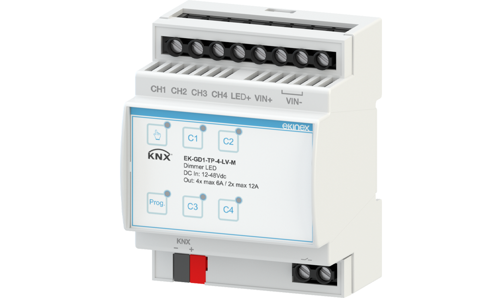
KNX 12/24/48 Vdc 4-channel Dimmer

Code: EK-GD1-TP-4-LV-M

Phase Out
KNX 12/24/48 Vdc 4-channel Dimmer

Description

The KNX 12/24/48 Vdc 4-channel dimmer EK-GD1-TP-4-LV allows PWM brightness control of LED loads.

Designed specifically for dimmable LED strips and loads, it is compatible with the KNX system and is suitable for monochrome strips.

Installation is simple via DIN-rail mounting, ensuring seamless integration into switch cabinets. The device has an integrated SELV 30 Vdc bus communication module, KNX certified.

Technical Data

Inputs

Constant Input Voltage12 / 24 / 48 Vdc
Supply VoltageMin: 10.8 Vdc .. max: 52.8 Vdc
Max. Input Current12 A

Outputs

PWM Voltage Output12 / 24 / 48 Vdc
Output Current6A for a single channel, or 12A for 2 channels connected in parallel
Output Channels4
Rated Power per Channel @12Vdc72 W
Rated Power per Channel @24Vdc144 W
Nominal Power per Channel @48Vdc288 W

Dimming

PWM Dimming ModeIn the range 250 Hz to 6 kHz

Supply & Delivery

The supply includes a terminal for connection to the bus line.

Functions and Features

Selection of PWM output frequency by ETS, from 250 Hz to 6 kHz
Parallel connection of outputs possible to increase output power
Fade on/off time, minimum and maximum brightness level, linear or logarithmic dimming curve settable via ETS
Configuration of behaviour after power reset, bus ON/OFF, unloading via ETS
Channels can be set by ETS as independent, parallel or with copy function from another channel
Blocking function, forced operation, staircase light, scenes, night, counter and logic functions for each channel, settable from ETS
Manual control with membrane buttons for local ON/OFF testing of channels 1-2-3-4: in manual mode, short press of a channel button activates/deactivates the load, pressing for at least 2 seconds causes the load to flash every 1 s approx.
Relay contact for switching off the AC/DC power supply when 12/24/48 Vdc outputs are switched off, or alternatively as relay for auxiliary output
Auxiliary output function via relay with status indication via KNX
Degree of protection: IP00 (IP20 in junction box or switchboard)
Power supply and load wiring: 0.2 to 4.0 mm2 (24 to 11 AWG) for single cable / 0.2 to 6 mm2 (24 to 9 AWG) for stranded cable

Configuration and Commissioning

A detailed description of the parameters can be found in the device's application manual. ETS5 or later versions are required for configuration and commissioning. Application programme for ETS: APEKGDXTPXLVM##.knxprod (## = version).

Technical Documentation

Datasheet

STEKGD1TP4LVM_EN• v. 1.0(25/09/2025)• PDF• 1,7 MB

Instructions

FISPEKGD1TP4LVM1• v. 1(16/06/2025)• PDF• 1,8 MB

Application Manual

MAEKGD12TP24LVM_EN• v. 1.0(20/06/2025)• PDF• 2 MB

Application Software for ETS

APEKGDXTPXLVM01• v. 1.0(17/06/2025)• KNXPROD• 168,6 KB

CE Conformity Declaration

CEEKGD1TP4LVM• v. 1.0(17/06/2025)• PDF• 874 KB

UKCA Statement

UKCAEKGD1TP4LVM• v. 1.0(16/06/2025)• PDF• 427,4 KB

Drawing

DQEKGD1TP4LVM• DXF• 3 MB