
Description
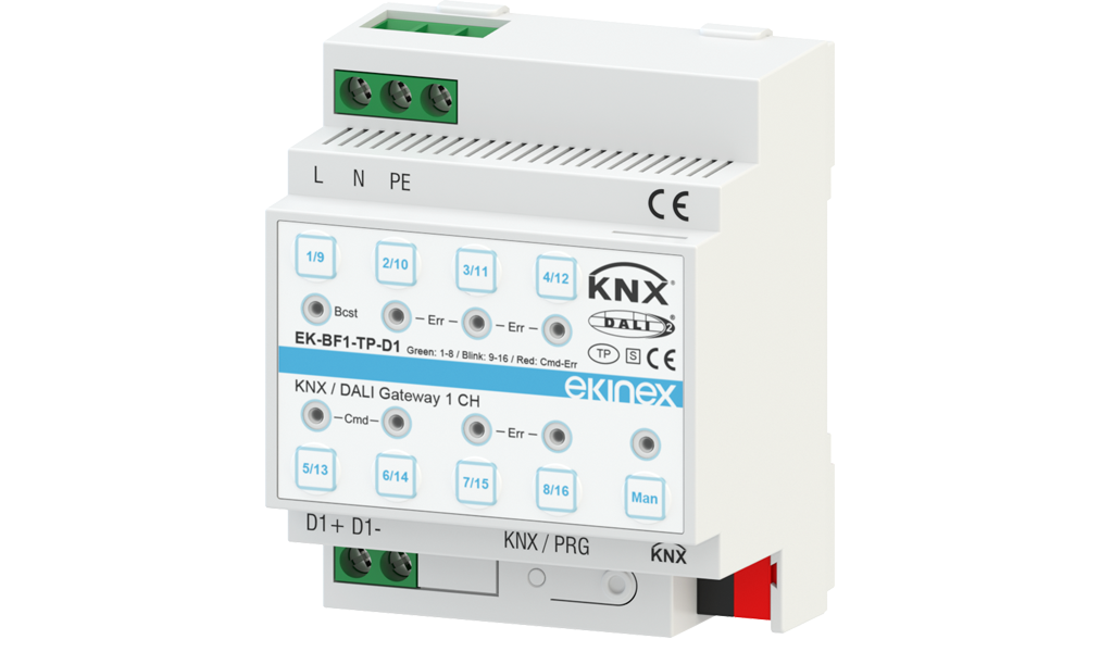
The EK-BF1-TP-D1/D2 KNX/DALI gateways are devices for controlling electronic control gear (ECG) with DALI interface (according to EN 62386) via the KNX installation bus. They convert switching and dimming commands sent from the KNX system to the DALI protocol and status information from the DALI bus to the KNX bus.
The device operates with 110-240 Vac/dc auxiliary power supply and conforms to EN 62386-101 and EN 62386-103 ed2 standards (DALI-2 certified with firmware >= 0.2.5).
Available Models
EK-BF1-TP-D1 (1 Channel)
Allows the addressing of up to 16 DALI groups and/or up to 64 individual electronic control gears (ECG).
EK-BF1-TP-D2 (2 Channels)
Allows the addressing of up to 2x16 DALI groups and/or up to 2x64 individual electronic ballasts (ECG).
Technical Data
Power Supply
Environmental Conditions
Design and Physical Characteristics
Connections
Scope of Delivery
Delivery includes a terminal block for connection to the bus, a terminal block cover and heat shrink tubing (1.2 x 2 cm) for bus cable insulation.
Functions and Features
Configuration and Commissioning
Configuration and commissioning by means of ETS application (v.5 and 6) for KNX parameters, and a dedicated DCA App for configuring DALI segments and ballasts.
Technical Documentation
Instruction sheet
FISPEKBF1TPD1D2IEXX00_P• v.1.0• PDF• 978 KB
Application manual
MAEKBF1TPD1D2_EN_v.1.1• v.1.1• PDF• 2.8 MB
Application program ETS
APEKBF1TPD1D2• v.5 & 6• ZIP• 319 KB
CE Declaration of conformity
CEEKBF1TPD1D2_v.1• v.1• ZIP• 1.2 MB
UKCA Declaration of conformity
UKCADCEKBF1TPD1D2_v.1• v.1• PDF• 431 KB
KNX Certificate (EK-BF1-TP-D1)
KNX_Certification_EK-BF1-TP-D1• PDF• 774 KB
KNX Certificate (EK-BF1-TP-D2)
KNX_Certification_EK-BF1-TP-D2• PDF• 774 KB
CAD Drawing (EK-BF1-TP-D1)
DSEKBF1TPD1• DXF• 10 MB
CAD Drawing (EK-BF1-TP-D2)
DSEKBF1TPD2• DXF• 11 MB