
Description
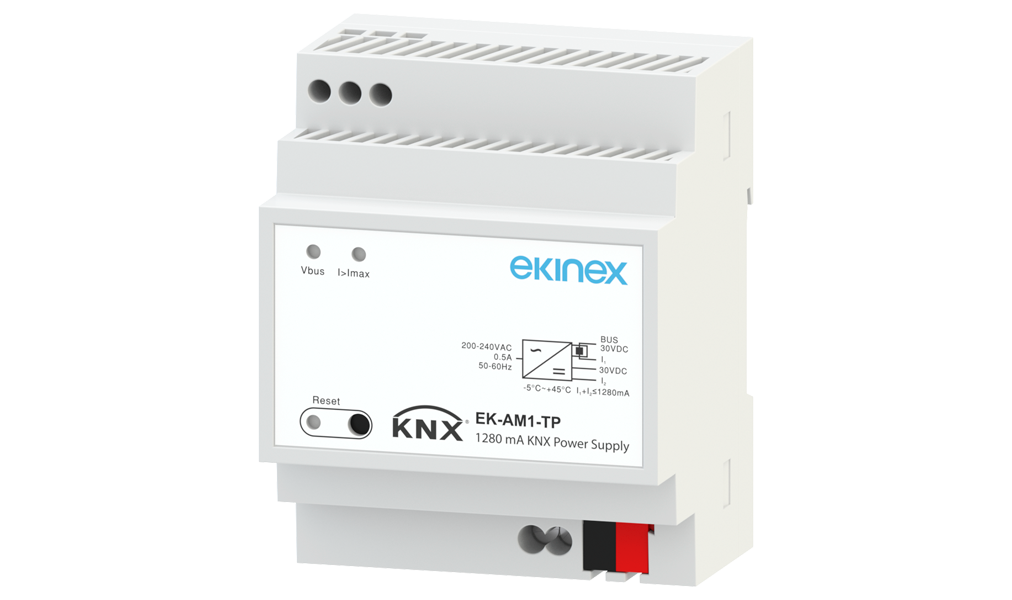
The Ekinex® EK-AM1-TP power supply produces and monitors the 30 Vdc voltage required for operation of the KNX bus system. A coil integrated in the device decouples the power supply from the bus line. The output has overload and short-circuit protection.
It has an additional 30 Vdc output that can be used for auxiliary supply of other SELV devices. The total current provided by the two outputs (KNX bus line and auxiliary power supply) cannot exceed 1280 mA. The device is capable of supporting short mains voltage interruptions (max. 200 ms).
Connections
- Connection to bus line via KNX terminal
- Auxiliary power connection via dedicated screw terminals
- Power supply connection via screw terminals
Technical Data
Functions / Features
Configuration and Commissioning
The power supply does not require configuration through the ETS® (Engineering Tool Software) program. The application program APEKAM1TP ##. knxprod (## = version) is available to add the power supply in an ETS project. To commission the appliance, simply power the input power line to which the device is connected. The lighting of the green LED marked with 'Vbus' indicates the regular operation of the device.
Technical Documentation
Datasheet
STEKAM1TP_EN• v. 1.0(05/04/2022)• PDF• 1,4 MB
Instructions Sheet
FISPAM1TPIEXXX0• v. 1.0(05/04/2022)• PDF• 544,4 KB
Application software for ETS
APEKAM1TP01• v. 1.0(19/10/2022)• KNXPROD• 85 KB
CE Conformity Declaration (v.1)
DIEKAM1TP• v. 1.0(13/05/2022)• PDF• 846 KB
CE Conformity Declaration
CEEKAM1TP• v. 1.0(13/10/2024)• PDF• 846,1 KB
UKCA Statement
UKCADCEKAM1TP• v. 1.0(01/07/2024)• PDF• 418,2 KB
KNX Certification
KNX_Certification_EK-AM1-TP• v. 1.0(19/04/2022)• PDF• 774,4 KB
Drawing (CAD)
DSEKAM1TP• DXF• 2,1 MB