
Description
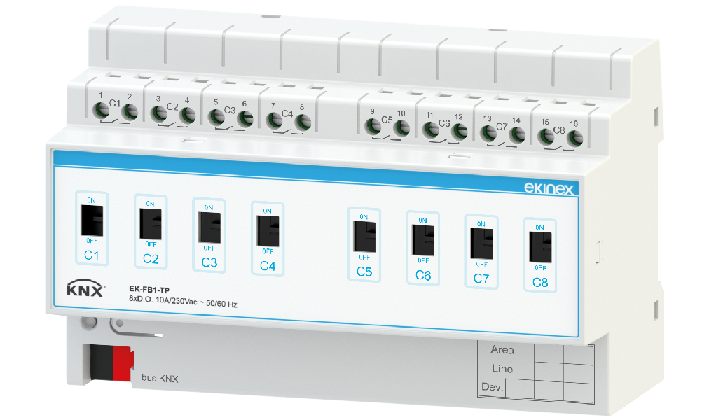
The Ekinex® EK-FB1-TP binary output allows to command 8 groups of loads independently; to this purpose, the device has outputs fitted with potential-free relays. The device’s latching relays guarantee the upkeep of command status even in the case of bus power failures.
The front levers indicate the status of each output channel and, in case of emergency, allow manual command (by means of a tool) of the loads. The device integrates a KNX bus communication module and is realized for mounting on a standard 35 mm DIN-rail. The device is supplied by the KNX bus and does not require auxiliary power supply.
Technical data
Power supply
- •30 Vdc voltage by KNX bus
- •Current consumption from bus < 12 mA
- •Power from bus 360 mW
Outputs
- •8 latch relays
- •Nominal voltage (Un): 100-230Vac, 50/60Hz
- •Nominal current (In): max 10 A (both @100Vac and @230Vac)
- •Switched power: 1000W @100Vac - 2200 W @230Vac
Delivery
Delivery includes a terminal block for connection to the bus.
Functions / Features
Configuration and commissioning
A detailed description of the parameters can be found in the application manual of the device. Configuration and commissioning require ETS5 or later versions. ETS application program: APEKFB1TP##.knxprod (## = release).
Technical documentation
Datasheet STEKFB1TP_EN
STEKFB1TP_EN_EKINEX_SPA• PDF• 1,3 MB
Instruction Sheet FISPFAB1TPIEXX0
FISPFAB1TPIEXX0_EKINEX_SPA• v. 1.0(23/11/2018)• PDF• 1,1 MB
Application manual MAEKFA1FB1TP_EN
MAEKFA1FB1TP_EN-v1.0_EKINEX_SPA• v. 1.0• PDF• 1,5 MB
Application software for ETS APEKFB1TP01
APEKFB1TP01• v. 01(12/12/2018)• KNXPROD• 163,4 KB
CE Conformity declaration CEEKFB1TP
CEEKFB1TP• PDF• 111,4 KB
KNX certification EK-FB1-TP
KNX_Certification_EK-FB1-TP• PDF• 299,7 KB
Drawing DSEKFB1TP
DSEKFB1TP• DXF• 955,3 KB